Appendix B: F75111N DIO & Watchdog Device
The Arrakis MK3, equipped with optional DIO ports, supports enhanced functionality through the use of a watchdog timer. This section provides guidance on how to program and utilize these features effectively.
Watchdog Timer Usage in DOS
The necessary software resources for programming the watchdog timer can be accessed from the Driver Download section:
Source File:
F75111_Dos_Src.rarBinary File:
F75111_Dos_Bin.rarAccess Credentials: Username & Password:
sf
Steps to Utilize the Demo Application:
Boot into the MS-DOS operating system.
Run the
75WDT.EXEexecutable file.Enter
1to activate the watchdog timer, or0to deactivate it.Specify the countdown duration in seconds for the timer, which will subsequently reset the computer.
Programming Example:
Below are examples of how to interact with the watchdog timer using I2C communication:
Activate and set the watchdog timer:
WriteI2CByte(I2CADDR, CONFIG, 0x03); // Configure watchdog timer function
WriteI2CByte(I2CADDR, WDT_TIMER, timer); // Set timer range 0-255 seconds
WriteI2CByte(I2CADDR, WDT_TIMER_CTL, 0x73); // Enable timer in second and pulse mode
Deactivate the watchdog timer:
WriteI2CByte(I2CADDR, WDT_TIMER_CTL, 0x00); // Disable watchdog timer
Sample code to pause operation using assembly language:
void pause(int time) {
    asm mov ah, 0h; // Set to read system time counter
    asm int 1ah;    // Read time from counter, store in DX
    asm add dx, time;
    asm mov bx, dx;
label:
    asm int 1ah;
    asm cmp bx, dx;
    asm jne label;
}
Watchdog Timer and DIO Configuration
You can find the necessary software resources in the Driver Download section under the DIO folder:
Source File:
F75111_DIOSrc.rarBinary File:
F75111_DemoBin.rarAccess Credentials: Username & Password:
sf
Using the Demo Application
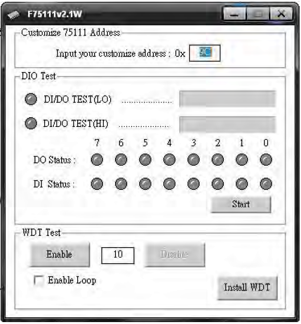
To test and configure the DIO and Watchdog Timer functions, follow these steps:
Click the
Startbutton to begin testing the DIO functionality.Click the
Enablebutton to activate the Watchdog Timer (WDT).Click the
Disablebutton to deactivate the WDT.To conduct a loop test, check the
Enable Loopbox and pressEnable.Use the
Install WDTbutton to configure the system to auto-run this application at boot. Click again to remove the auto-run setting. An icon indicates when this setting is active.
Command Functions
Watchdog Timer Initialization: Configure the initial internal F75111 port settings and enable necessary functions.
Digital Output (DO): Set digital output values.
Digital Input (DI): Retrieve digital input values.
Watchdog Timer Enable/Disable: Activate or deactivate the Watchdog Timer.
Examples of Code Implementation:
1. Initialize Watchdog Timer and Ports:
// Initialize F75111 internal settings for input and output configurations
InitInternalF75111();
2. Set Output Values:
// Output a specific byte value to digital output
InterDigitalOutput(byteValue);
3. Retrieve Input Values:
// Get input values from digital input
BYTE inputStatus = InterDigitalInput();
4. Manage Watchdog Timer:
// Enable the Watchdog Timer with a specific timeout
F75111_SetWDTEnable(timerValue);
// Disable the Watchdog Timer
F75111_SetWDTDisable();
IO Device: F75111 VB6 under Windows
You can find the necessary software resources in the Driver Download section under the DIO folder:
Source File:
75111_VB_v10.rarBinary File:
75111_VB_Src.rar111_DemoBin.rarAccess Credentials: Username & Password:
sf
How to Use the Demo Application
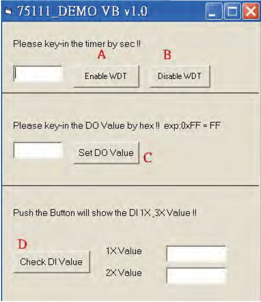
A. Enable WDT Timer: Enter the desired time in seconds, then the system will reboot after the specified time. B. Disable WDT Timer: Press the button to clear the WDT timer value. C. Set DO Value: Enter the DO value in hexadecimal and press the button. D. Check DI Value: The right-side text boxes display the DI 1X & 2X values when the button is pressed.
SDK Function Introduction
Function EnableWDT:
Function EnableWDT(timer As Integer)
    Call WriteI2CByte(&H3, &H3)
    Call WriteI2CByte(&H37, timer)
    Call WriteI2CByte(&H36, &H73)
End Function
Function DisableWDT:
Function DisableWDT()
    Call WriteI2CByte(&H36, &H0)
End Function
Function SetDOValue:
Function SetDOValue(dovalue As Integer)
    Call WriteI2CByte(&H23, &H0)
    Call WriteI2CByte(&H20, &HFF)
    Call WriteI2CByte(&H2B, &HFF)
    Call WriteI2CByte(&H21, dovalue)
End Function
Function CheckDIValue:
Function CheckDIValue()
    Dim GPIO1X As Integer
    Dim GPIO3X As Integer
    Dim DI1Xhex As String
    Dim DI3Xhex As String

    Call ReadI2CByte(&H12, GPIO1X)
    Call ReadI2CByte(&H42, GPIO3X)

    DI1Xhex = Hex(GPIO1X)
    DI3Xhex = Hex(GPIO3X)

    Text3.Text = "0x" + DI1Xhex
    Text4.Text = "0x" + DI3Xhex
End Function
Watchdog Timer and DIO under Linux
You can find the necessary software resources in the Driver Download section under the DIO folder:
Source File:
F75111v2.0L.tar.gzBinary File:
F75111v2.0LBin.tar.gzAccess Credentials: Username & Password:
sf
How to Compile Source Code
Compile Source Code with Code::Blocks
Install Code::Blocks with the command:
apt-get install codeblocksOpen the existing project (
F75111.cbp) in Code::Blocks and click the compile buttonAdd the option
'pkg-config --libs gtk+-2.0 gthread-2.0'inProject->Build Options->Linker Settings->Other linker options
Compile Source Code with
makeNavigate to the F75111 directory:
cd F75111Compile the source code:
makeExecute the binary file:
src/f75111
How to Use the Demo Application
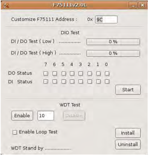
Press the
Startbutton to test the DIO functionPress the
Enablebutton to test the WDT functionPress the
Disablebutton to disable the WDTCheck the
Enable Loopbox and pressEnableto perform a WDT loop testPress
Installto set the system to autorun this application when booting, and pressUninstallto remove it from autorunIf WDT is enabled, the system icon will blink
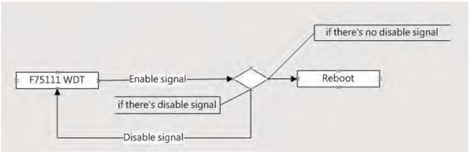
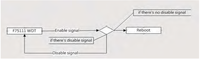
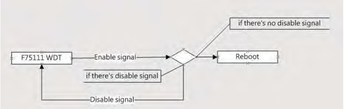
F75111 will send F75111_SetWDTEnable(BYTE byteTimer) with a parameter timer. If there is no disable signal (F75111_SetWDTDisable()) before the timer counts down to 0, the system will reboot. If a disable signal is received, it will resend the enable WDT signal to prevent a reboot loop.
Introduction
IO Function in SMBus.c:
void SMBusIoWrite(BYTE byteOffset, BYTE byteData) {
    outb(byteData, m_SMBusMapIoAddr + byteOffset);
}

BYTE SMBusIoRead(BYTE byteOffset) {
    DWORD dwAddrVal;
    dwAddrVal = inb(m_SMBusMapIoAddr + byteOffset);
    return (BYTE)(dwAddrVal & 0x0FF);
}
Initialize Internal F75111:
void F75111::InitInternalF75111() {
    this->Write_Byte(F75111_INTERNAL_ADDR, GPIO1X_CONTROL_MODE, 0x00); // Set GPIO1X to Input function
    this->Write_Byte(F75111_INTERNAL_ADDR, GPIO3X_CONTROL_MODE, 0x00); // Set GPIO3X to Input function
    this->Write_Byte(F75111_INTERNAL_ADDR, GPIO2X_CONTROL_MODE, 0xFF); // Set GPIO2X to Output function
    this->Write_Byte(F75111_INTERNAL_ADDR, F75111_CONFIGURATION, 0x03); // Enable WDT OUT function
}
Set Output Value:
void F75111::InterDigitalOutput(BYTE byteValue) {
    BYTE byteData = 0;
    byteData = (byteData & 0x01) ? byteValue + 0x01 : byteValue;
    byteData = (byteData & 0x02) ? byteValue + 0x02 : byteValue;
    byteData = (byteData & 0x04) ? byteValue + 0x04 : byteValue;
    byteData = (byteData & 0x80) ? byteValue + 0x08 : byteValue;
    byteData = (byteData & 0x40) ? byteValue + 0x10 : byteValue;
    byteData = (byteData & 0x20) ? byteValue + 0x20 : byteValue;
    byteData = (byteData & 0x10) ? byteValue + 0x40 : byteValue;
    byteData = (byteData & 0x08) ? byteValue + 0x80 : byteValue; // Get value bit by bit
    this->Write_Byte(F75111_INTERNAL_ADDR, GPIO2X_OUTPUT_DATA, byteData); // Write byteData value via GPIO2X output pin
}
Get Input Value:
BYTE F75111::InterDigitalInput() {
    BYTE byteGPIO1X = 0;
    BYTE byteGPIO3X = 0;
    BYTE byteData = 0;
    this->Read_Byte(F75111_INTERNAL_ADDR, GPIO1X_INPUT_DATA, &byteGPIO1X); // Get value from GPIO1X
    this->Read_Byte(F75111_INTERNAL_ADDR, GPIO3X_INPUT_DATA, &byteGPIO3X); // Get value from GPIO3X
    byteGPIO1X = byteGPIO1X & 0xF0; // Mask unuseful value
    byteGPIO3X = byteGPIO3X & 0x0F; // Mask unuseful value
    byteData = (byteGPIO1X & 0x10) ? byteData + 0x01 : byteData;
    byteData = (byteGPIO1X & 0x80) ? byteData + 0x02 : byteData;
    byteData = (byteGPIO1X & 0x40) ? byteData + 0x04 : byteData;
    byteData = (byteGPIO3X & 0x01) ? byteData + 0x08 : byteData;
    byteData = (byteGPIO3X & 0x02) ? byteData + 0x10 : byteData;
    byteData = (byteGPIO3X & 0x04) ? byteData + 0x20 : byteData;
    byteData = (byteGPIO3X & 0x08) ? byteData + 0x40 : byteData;
    byteData = (byteGPIO1X & 0x20) ? byteData + 0x80 : byteData; // Get correct DI value from GPIO1X & GPIO3X
    return byteData;
}
Enable WatchDog:
void F75111_SetWDTEnable(BYTE byteTimer) {
    WriteByte(F75111_INTERNAL_ADDR, WDT_TIMER_RANGE, byteTimer); // Set WatchDog range and timer
    WriteByte(F75111_INTERNAL_ADDR, WDT_CONFIGURATION, WDT_TIMEOUT_FLAG | WDT_ENABLE | WDT_PULSE | WDT_PSWIDTH_100MS);
    // Enable WatchDog, Setting WatchDog configure
}
Disable WatchDog:
void F75111_SetWDTDisable() {
    WriteByte(F75111_INTERNAL_ADDR, WDT_CONFIGURATION, 0x00); // Disable WatchDog
}