Mainboard Overview
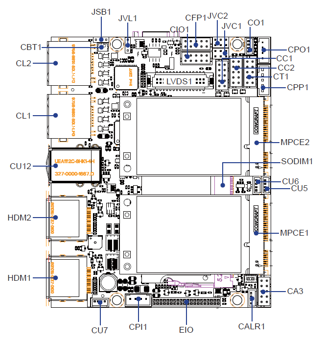
Mainboard Layout Overview
View the detailed layout to understand the location of connectors on the mainboard:
Jumper Descriptions
Jumper Configurations:
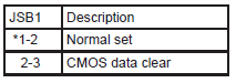
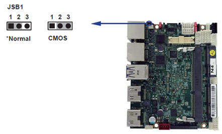
JSB1: Clears CMOS data
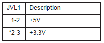
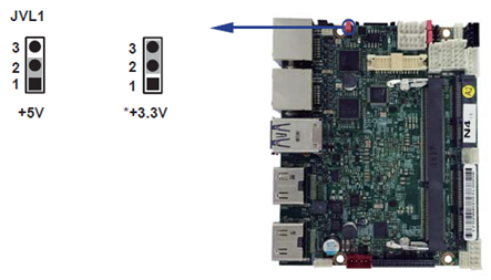
JVL1: Selects power for the LCD panel
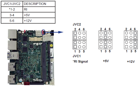
JVC1/JVC2: Configures COM1/2 ring indicator and power selection
Jumper Settings Explained
Jumpers manage electrical connections on a mainboard. A jumper is set to “ON” when a plastic cap bridges two pins, creating a closed circuit. It is set to “OFF” when the cap is removed, opening the circuit. Some jumpers include three pins (1, 2, and 3), allowing configurations between pins 1-2 or 2-3. The illustration below demonstrates various jumper settings:
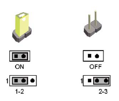
All jumpers are preset to their default configurations, marked with an asterisk (*) in this guide, either as ON (with cap) or OFF (without cap).
Detailed Jumper Settings
JSB1: CMOS Data Reset
To maintain or clear the motherboard’s CMOS settings:
Power off the system and disconnect all power sources.
Disconnect the 12V DC power cable.
Set JSB1 jumper between pins 1 and 2 to clear CMOS.
Reset JSB1 to its default setting (typically pin 1-2 closed).
Reconnect the 12V DC power cable.
This procedure is typically used for troubleshooting or if the BIOS password is forgotten.
JSB1 Illustrations:
JVL1: LCD Panel Power Selection
Adjust JVL1 to select the appropriate power setting for your LCD panel.
JVL1 Settings Visualization:
JVC1/JVC2: COM Port Configuration
Set JVC1 and JVC2 to configure power and signal settings for COM1 and COM2 ports.
JVC1/JVC2 Configuration: