Product Specifications
Technical Details
Feature |
Specification |
Details |
|---|---|---|
Processor |
CPU |
Intel Atom® Quadcore E3950, 1.6/2.0 GHz (Standard) |
Memory |
RAM |
up to 8GB DDR3L SoDIMM |
Storage Options |
mSATA |
1 mSATA 2.0 Slot |
Security |
TPM |
TPM 2.0 with TrEE 1.1 |
I/O Ports |
HDMI |
1 HDMI port |
DisplayPort |
1 DisplayPort |
|
Gigabit Ethernet |
2x RJ45 ports |
|
USB 3.0 |
4 ports |
|
Serial Ports |
2x RS232/RS485, optional expansion for 2 additional |
|
Digital I/O |
1 DI, 12-24V |
|
Connectivity |
Ethernet |
Dual Intel i210IT LAN chip (Gigabit) |
WLAN (optional) |
Optional, via mPCIe |
|
WWAN (optional) |
Optional 4G/5G via USB |
|
Expansion |
SIM Slots |
2 push-push type SIM slots (available with 4G/5G modules) |
Additional |
Audio and Other |
Line in/out, Digital I/O, CAN (optional) |
Watchdog Timer |
Programmable from 1 to 255 seconds |
|
Environmental |
Operating Temperature |
-20° to 70° C |
Storage Temperature |
-20° to 80° C |
|
Humidity |
5% to 95% non-condensing |
|
Power |
Supply |
9 - 36 V DC (+/-10% tolerance), 4-pin terminal block and DC jack |
Adapter |
Optional 60W, 24V/5A external, CR1220 CMOS battery |
|
Mounting |
Options |
DIN-Rail mounting kits available |
Operating System |
Compatibility |
Windows 10, Ubuntu Linux, others upon request |
Physical Build |
Material/Color |
Steel / Aluminum |
Ingress Protection |
IP20 |
|
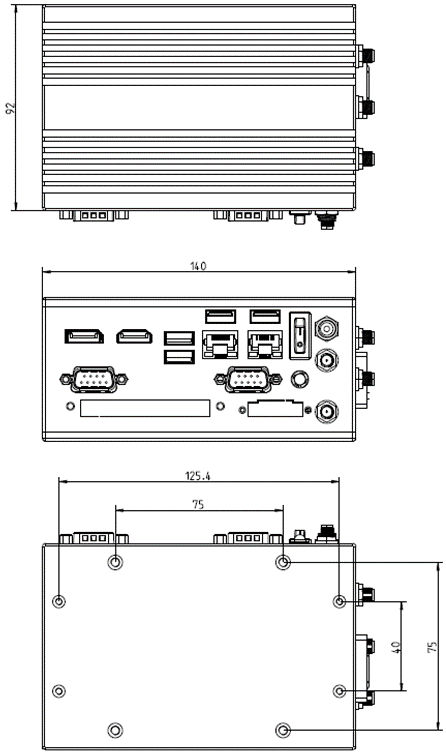
Dimensions |
64 x 140 x 92 mm |
|
Weight |
800 g |
System Information

Being a powerful, yet small fanless system, the Arrakis Pico Mk4 may reach very high surface temperatures in excess of 60°C/140°F with risk of injury. Users should ensure sufficient protection against touching.
To allow for sufficient heat removal we recommend: 30mm distance on either side of the Arrakis Pico Mk4 when mounted on a DIN-Rail 100mm headroom above the Arrakis Pico Mk4 when mounted horizontally. The heatsink should be on top.
System Drawing
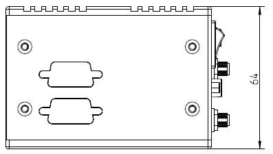
Bottom side
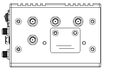
Top side
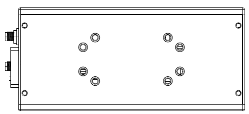
Rear side
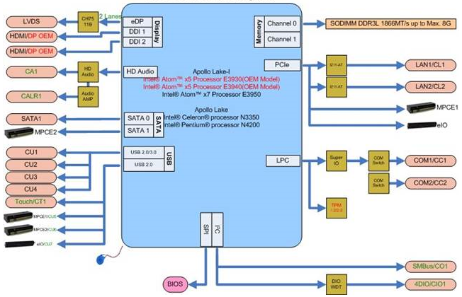
Mainboard Block Diagram
This block diagram describes the relationship among all interfaces and modules on the mainboard.